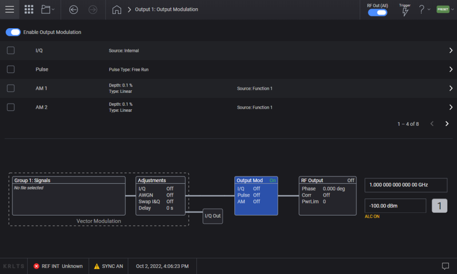
This topic describes the parameters of the ![]() Output Modulation block.
Output Modulation block.
Enables or disables the currently active modulation type of the indicated channel. Most modulation types can be simultaneously enabled except FM with ΦM. An annunciator on the signal generator always indicates whether modulation is on or off.
|
GUI Location |
Modulation |
|
SCPI Command |
[:SOURce][:RF<channel>]:OUTPut:MODulation[:STATe] ON|OFF|1|0 [:SOURce][:RF<channel>]:OUTPut:MODulation[:STATe]? |
|
SCPI Example |
OUTP:MOD OFF |
|
Preset |
ON |
|
State Saved |
Yes |
|
Choices |
OFF | ON |
|
Initial S/W Revision |
A.01.00 |
Selecting this check box in this row performs the same function as I/Q Modulation On. If you click or tap elsewhere in this row, the I/Q Setup screen appears, allowing you to configure parameters specific to I/Q modulation.
Enables or disables the I/Q modulation of the RF Output.
For M9484C, I/Q Modulation cannot be enabled at the same time as Pulse Modulation. Enabling I/Q modulation disables pulse modulation; likewise, enabling pulse modulation disables I/Q modulation.
|
GUI Location |
Output Modulation > I/Q Modulation On |
|
SCPI Command |
[:SOURce][:RF<channel>]:DM:STATe ON|OFF|1|0 [:SOURce][:RF<channel>]:DM:STATe? |
|
SCPI Example |
DM:STAT ON DM:STAT? |
|
Preset |
OFF |
|
Couplings |
When Enable Amplitude Control is turned ON, I/Q Modulation is set to OFF. When I/Q Modulation is turned ON, Enable Amplitude Control is set to OFF. When I/Q Modulation Source is Internal:
For M9484C, enabling I/Q Modulation disables Pulse Modulation. |
|
Notes |
When setting State to ON turns another feature off, the warning is raised -221, "Settings conflict; I/Q Modulation in use, Pulse Modulation has been turned off." |
|
State Saved |
Yes |
|
Initial S/W Revision |
A.01.00 |
|
Modified S/W Revision |
A.07.00, A.11.00 |
|
History |
Coupling with I/Q Output Amplitude Control added with A.07.00. M9484C added with A.11.00 |
Selects the I/Q modulation source.
For instruments with Option EXT, selects either an internal or external I/Q modulation source.
EXTernal: Routes the applied signals from the I and Q input connectors, or -I/+I/-Q/+Q for differential input connectors, to modulate the RF carrier.
INTernal: Selects the internal baseband generator, the Signal, as the source for the I/Q modulation of the RF carrier.
|
GUI Location |
Output Modulation > I/Q > I/Q DC Alignment > I/Q Modulation Source |
|
SCPI Command |
[:SOURce][:RF<channel>]:DM:SOURce EXTernal|INTernal [:SOURce][:RF<channel>]:DM:SOURce? |
|
SCPI Example |
DM:SOUR EXT DM:SOUR? |
|
Notes |
For instruments without Option EXT, the source is INTernal and not changeable. Attempting to set EXTernal raises error -221, Settings Conflict; option EXT is required. |
|
Preset |
INTernal |
|
Choices |
External | Internal |
|
Couplings |
When Enable Amplitude Control is turned ON, I/Q Modulation Source is set to Internal. When Enable Amplitude Control is ON and you attempt to set I/Q Modulation Source to External, the following error occurs: -221,"Settings conflict; External I/Q not allowed while I/Q Amplitude Control is enabled." |
|
State Saved |
Yes |
|
Initial S/W Revision |
A.01.00 |
Applies to the M9383B VXG-m and M9384B VXG only.
Invokes an I/Q DC alignment. The instrument’s in-band images and LO feedthrough can negatively impact EVM performance. I/Q DC alignment should be performed when you modulate at a new frequency, or the temperature changes by a few degrees from the last time the alignment was performed.
|
GUI Location |
Output Modulation > I/Q > I/Q DC Alignment > Perform Alignment |
|
SCPI Command |
[:SOURce][:RF<channel>]:CALibration:IQ:DC |
|
SCPI Example |
CAL:IQ:DC |
|
Notes |
For M9484C: This command is accepted with no action performed, sending the SCPI command does not generate an error. |
|
Initial S/W Revision |
A.01.00 |
Whenever the best possible EVM performance is required or in use cases where DC and image rejection of I/Q modulation impact measurement results. I/Q DC alignment should be used after the instrument has been warmed up or whenever significant room temperature changes occur. It should be run at least once for each frequency the instrument set to. After each alignment is run, the calibration data is cached for each set frequency. This caching allows you to tune from frequency A to frequency B and back to frequency A with the most recent DC-alignment applied. If the instrument is power cycled, it is recommended that you perform these I/Q DC alignments again. You can also empirically determine how often this DC alignment should be performed, based on how sensitive your measurements are and how much temperature variation you observe over time.
Applies to the M9383B VXG-m and M9384B VXG only.
Returns the I/Q DC Alignment data at the current frequency to the factory default. You can use this when diagnosing signal quality issues. However, it is recommended to simply run the I/Q DC Alignment anew rather than clearing the alignment.
|
GUI Location |
Output Modulation > I/Q > I/Q DC Alignment > Clear Alignment |
|
SCPI Command |
[:SOURce][:RF<channel>]:CALibration:IQ:DC:CLEar |
|
SCPI Example |
CAL:IQ:DC:CLE |
|
Notes |
For M9484C: This command is accepted with no action performed, sending the SCPI command does not generate an error. |
|
Initial S/W Revision |
A.01.00 |
Applies to the M9383B VXG-m and M9384B VXG only.
Invokes an I/Q Skew alignment. The instrument’s parasitic time delay (skew) between the I and Q channels can vary with time and temperature. I/Q Skew alignment should be performed when the temperature changes by a few degrees from the last time the alignment was performed.
|
GUI Location |
Output Modulation > I/Q > Skew Alignment > Perform Alignment |
|
SCPI Command |
[:SOURce][:RF<channel>]:CALibration:IQ:TSKew |
|
SCPI Example |
CAL:IQ:TSK |
|
Notes |
For M9484C: This command is accepted with no action performed, sending the SCPI command does not generate an error. |
|
Initial S/W Revision |
A.01.00 |
Whenever the best possible wideband EVM performance is required (approximately 1 GHz or greater) or in use cases where wideband I/Q skew impacts measurement results. In most cases, the I/Q skew alignment should not be run often. However, the baseband I/Q paths in the VXG signal generator can be temperature sensitive and, depending on the I/Q data being played from the arbitrary waveform generator, there is a self-heating thermal gradient that could occur between the I and Q path. (This is especially true for OFDM-based I/Q waveforms having a bandwidth greater than 1 GHz.) This thermal gradient can result in one to two pico-seconds of time skew at the extreme bandwidth edges of the I/Q modulation. Thermal mitigation techniques have been deployed to minimize this effect, however, you may empirically decide to run this calibrations more often, if needed.
Applies to the M9383B VXG-m and M9384B VXG only.
Returns the I/Q Time Skew Alignment data to the factory default. You can use this when diagnosing signal quality issues. However, it is recommended to simply run the I/Q Time Skew Alignment anew rather than clearing the alignment.
|
GUI Location |
Output Modulation > I/Q > Skew Alignment > Clear Alignment |
|
SCPI Command |
[:SOURce][:RF<channel>]:CALibration:IQ:TSKew:CLEar |
|
SCPI Example |
CAL:IQ:TSK:CLE |
|
Notes |
For M9484C: This command is accepted with no action performed, sending the SCPI command does not generate an error. |
|
Initial S/W Revision |
A.01.00 |
The check box in this row performs the same function as AM n On. If you click or tap elsewhere in this row, the AM Setup screen appears, allowing you to configure parameters specific to AM modulation.
Enables or disables the amplitude modulation for the selected path.
When ALC is on, AM cannot be turned on.
AM State cannot be turned on when the source of the corresponding AM path (1 or 2) is used and when AM path is on.
|
GUI Location |
Output Modulation > AM n > AM n On |
|
SCPI Command |
[:SOURce][:RF<channel>]:AM{1:2}:STATe ON|OFF|1|0 [:SOURce][:RF<channel>]:AM{1:2}:STATe? |
|
SCPI Example |
AM:STAT ON AM:STAT? |
|
Preset |
OFF |
|
State Saved |
Yes |
|
Choices |
OFF | ON |
|
Initial S/W Revision |
A.01.00 |
Sets the AM type to linear or exponential AM.
LINear: Selects linear AM type with depth values in units of percent/volt.
EXPonential: Selects exponential AM type with depth values in units of dB/volt.
|
GUI Location |
Output Modulation > AM n > Type Linear or Exponential |
|
SCPI Command |
[:SOURce][:RF<channel>]:AM{1:2}:TYPE LINear|EXPonential [:SOURce][:RF<channel>]:AM{1:2}:TYPE? |
|
SCPI Example |
AM2:TYPE LIN AM2:TYPE? |
|
Preset |
LINear |
|
State Saved |
Yes |
|
Choices |
Linear | Exponential |
|
Initial S/W Revision |
A.01.00 |
Sets the source to generate the amplitude modulation.
External: Selects an externally applied signal as the modulation Input
Function 1: Selects function generator 1 as the modulation source.
Function 2: Selects function generator 2 as the modulation source.
Dual Function : Selects the dual function generator as the modulation source.
Noise 1: Selects the noise generator 1 as the modulation source.
Noise 2: Selects the noise generator 1 as the modulation source.
|
GUI Location |
Output Modulation > AM n > Source |
|
SCPI Command |
[:SOURce][:RF<channel>]:AM{1:2}:SOURce FUNCtion1|FUNCtion2|DUAL|NOISe1|NOISe2|EXTernal [:SOURce][:RF<channel>]:AM{1:2}:SOURce? |
|
SCPI Example |
AM2:SOUR DUAL AM2:SOUR? |
|
Preset |
FUNCtion1 |
|
State Saved |
Yes |
|
Choices |
External | Function 1 | Function 2 | Dual Function | Noise 1 | Noise 2 |
|
Initial S/W Revision |
A.01.00 |
Sets the linear amplitude modulation depth for the selected AM path in percent.
Refer to Depth Increment for setting the value associated with UP and DOWN choices.
|
GUI Location |
Output Modulation > AM n > Type set to Depth > Depth |
|
SCPI Command |
[:SOURce][:RF<channel>]:AM{1:2}[:DEPTh][:LINear] <real> [:SOURce][:RF<channel>]:AM{1:2}[:DEPTh][:LINear]? |
|
SCPI Example |
AM 30 AM? |
|
Preset |
0.1 |
|
State Saved |
Yes |
|
Range |
0 to 100 |
|
Resolution |
0.1 |
|
Initial S/W Revision |
A.01.00 |
Depth - Exponential
Sets the exponential amplitude modulation depth for the selected AM path in dB.
Refer to Depth Increment for setting the value associated with UP and DOWN choices.
|
GUI Location |
Output Modulation > AM n > Type set to Exponential > Depth |
|
SCPI Command |
[:SOURce][:RF<channel>]:AM{1:2}[:DEPTh]:EXPonential <rel_ampl> [:SOURce][:RF<channel>]:AM{1:2}[:DEPTh]:EXPonential? |
|
SCPI Example |
AM:EXP 30 AM:EXP? |
|
Preset |
40 |
|
State Saved |
Yes |
|
Range |
0 to 40 |
|
Resolution |
0.01 |
|
Initial S/W Revision |
A.01.00 |
Remote command only.
Sets the increment for linear AM depth step.
The value set by this command is used with the UP and DOWN choices for the AM depth setting.
The setting enabled by this command is not affected by signal generator power-on, preset, or *RST.
|
SCPI Command |
[:SOURce][:RF<channel>]:AM{1:2}[:DEPTh]:STEP[:INCRement] <real> [:SOURce][:RF<channel>]:AM{1:2}[:DEPTh]:STEP[:INCRement]? |
|
SCPI Example |
AM:STEP 5 AM:STEP? |
|
State Saved |
No |
|
Preset |
5 |
|
Range |
0.1 to 100 |
|
Initial S/W Revision |
A.01.00 |
Sets the coupling for the amplitude modulation source through the selected external input connector.
AC: This choice will only pass AC signal components. Any DC offset will be removed.
DC: This choice will pass both AC and DC signal components.
The command does not change the currently active source or switch the current modulation on or off. The modulating signal may be the sum of several signals, either internal or external sources.
|
GUI Location |
Output Modulation > AM n > Source set to External > Coupling AC or DC |
|
SCPI Command |
[:SOURce][:RF<channel>]:AM{1:2}:EXTernal:COUPling AC|DC [:SOURce][:RF<channel>]:AM{1:2}:EXTernal:COUPling? |
|
SCPI Example |
AM:EXT:COUP AC AM:EXT:COUP? |
|
Preset |
DC |
|
State Saved |
Yes |
|
Choices |
DC | AC |
|
Initial S/W Revision |
A.01.00 |
Sets the input impedance for the externally applied AM input
In case the set impedance value is not 1000000 or 600, the default value (50) will be used.
|
GUI Location |
Output Modulation > AM n > Source set to External > Impedance 50 Ohm, 600 Ohm or 1M Ohm |
|
SCPI Command |
[:SOURce][:RF<channel>]:AM{1:2}:EXTernal:IMPedance 50|600|1000000 [:SOURce][:RF<channel>]:AM{1:2}:EXTernal:IMPedance? |
|
SCPI Example |
AM:EXT:IMP 600 AM:EXT:IMP? |
|
Preset |
50 |
|
State Saved |
Yes |
|
Initial S/W Revision |
A.01.00 |
Sets the amplitude modulation rate for the waveform on the selected internal function generator.
Sine: 10 MHz
Otherwise: 1 MHz
|
GUI Location |
Output Modulation > AM n > Source set to Function 1 or Function 2 > Frequency |
|
SCPI Command |
[:SOURce][:RF<channel>]:AM{1:2}:INTernal:FUNCtion{1:2}:FREQuency <freq> [:SOURce][:RF<channel>]:AM{1:2}:INTernal:FUNCtion{1:2}:FREQuency? |
|
SCPI Example |
AM:INT:FUNC:FREQ 30 AM:INT:FUNC:FREQ? |
|
Preset |
400 Hz |
|
State Saved |
Yes |
|
Range |
0.1 Hz to 1 MHz |
|
Initial S/W Revision |
A.01.00 |
Remote command only.
Sets the step increment for the internal frequency modulation.
The setting enabled by this command is not affected by signal generator power-on, preset, or *RST.
|
SCPI Command |
[:SOURce][:RF<channel>]:AM:INTernal:FREQuency:STEP[:INCRement] <freq> [:SOURce][:RF<channel>]:AM:INTernal:FREQuency:STEP[:INCRement]? |
|
SCPI Example |
AM:INT:FREQ:STEP 3 MHZ AM:INT:FREQ:STEP? |
|
Preset |
500 Hz |
|
State Saved |
Persistent, survives preset and power cycle but not saved in the instrument state. |
|
Range |
0.1 Hz to 6.25 MHz |
|
Initial S/W Revision |
A.01.00 |
Sets the phase offset (in radians) of the AM signal. The value can be set in degrees as well via both GUI and SCPI.
|
GUI Location |
Output Modulation > AM n > Source set to Function 1 or Function 2 > Phase Offset |
|
SCPI Command |
[:SOURce][:RF<channel>]:AM{1:2}:INTernal:FUNCtion{1:2}:POFFset <real> [:SOURce][:RF<channel>]:AM{1:2}:INTernal:FUNCtion{1:2}:POFFset? |
|
SCPI Example |
AM:INT:FUNC:POFF 2 AM:INT:FUNC:POFF? |
|
Preset |
0 |
|
State Saved |
Yes |
|
Range |
-6.29 to 6.29 |
|
Resolution |
0.001 |
|
Initial S/W Revision |
A.01.00 |
Sets the AM waveform type.
|
GUI Location |
Output Modulation > AM n > Source set to Function 1 or Function 2 > Shape |
|
SCPI Command |
[:SOURce][:RF<channel>]:AM{1:2}:INTernal:FUNCtion{1:2}:SHAPe SINE|TRIangle|PULSe|RAMP [:SOURce][:RF<channel>]:AM{1:2}:INTernal:FUNCtion{1:2}:SHAPe? |
|
SCPI Example |
AM2:INT:FUNC:SHAP TRI AM2:INT:FUNC:SHAP? |
|
Preset |
SINE |
|
State Saved |
Yes |
|
Choices |
Sine | Triangle | Pulse | Ramp |
|
Initial S/W Revision |
A.01.00 |
Remote command only.
Sets the ramp direction when :AM{1:2}:INTernal:FUNCtion{1:2}:SHAPe is set to RAMP.
|
SCPI Command |
[:SOURce][:RF<channel>]:AM{1:2}:INTernal:FUNCtion{1:2}:SHAPe:RAMP POSitive|NEGative [:SOURce][:RF<channel>]:AM{1:2}:INTernal:FUNCtion{1:2}:SHAPe:RAMP? |
|
SCPI Example |
AM2:INT:FUNC:SHAP:RAMP POS AM2:INT:FUNC:SHAP:RAMP? |
|
Preset |
POSitive |
|
State Saved |
Yes |
|
Initial S/W Revision |
A.01.00 |
Sets the duty cycle in percent for Pulse mode.
|
GUI Location |
Output Modulation > AM n > Source set to Function 1 or Function 2 > Shape set to Pulse > Duty Cycle |
|
SCPI Command |
[:SOURce][:RF<channel>]:AM{1:2}:INTernal:FUNCtion{1:2}:DCYCle <real> [:SOURce][:RF<channel>]:AM{1:2}:INTernal:FUNCtion{1:2}:DCYCle? |
|
SCPI Example |
AM:INT:FUNC:DCYC 20 AM:INT:FUNC:DCYC |
|
Preset |
50 |
|
State Saved |
Yes |
|
Range |
0 to 100 |
|
Resolution |
0.01 |
|
Initial S/W Revision |
A.01.00 |
Sets the amplitude for tones of the internal dual function generator source as a percent of the peak analog modulation amplitude.
Setting the amplitude of one tone automatically set the other tone to make up the remaining amplitude.
|
GUI Location |
Output Modulation > AM n > Source set to Dual Function > Amp Percent n |
|
SCPI Command |
[:SOURce][:RF<channel>]:AM{1:2}:INTernal:DUAL:FUNCtion[1]:2:AMPLitude:PERCent <real> [:SOURce][:RF<channel>]:AM{1:2}:INTernal:DUAL:FUNCtion[1]:2:AMPLitude:PERCent? |
|
SCPI Example |
AM:INT:DUAL:FUNC2:AMPL:PERC 50 AM:INT:DUAL:FUNC2:AMPL:PERC? |
|
Preset |
50 |
|
State Saved |
Yes |
|
Range |
0 to 100 |
|
Resolution |
0.1 |
|
Initial S/W Revision |
A.01.00 |
Sets the frequency of tone 1 (default) or tone 2 of the internal dual function generator source.
|
GUI Location |
Output Modulation > AM n > Source set to Dual Function > Frequency n |
|
SCPI Command |
[:SOURce][:RF<channel>]:AM{1:2}:INTernal:DUAL:FUNCtion{1:2}:FREQuency <freq> [:SOURce][:RF<channel>]:AM{1:2}:INTernal:DUAL:FUNCtion{1:2}:FREQuency? |
|
SCPI Example |
AM:INT:DUAL:FUNC:FREQ 30 AM:INT:FUNC:FREQ? |
|
Preset |
400 Hz |
|
State Saved |
Yes |
|
Min |
0.1 Hz to 1 MHz |
|
Resolution |
0.1 Hz |
|
Initial S/W Revision |
A.01.00 |
Sets the phase offset in degrees or radians of tone 2 in relation to tone 1 of the internal dual function generator source.
|
GUI Location |
Output Modulation > AM n > Source set to Dual Function > Phase Offset 2 |
|
SCPI Command |
[:SOURce][:RF<channel>]:AM{1:2}:INTernal:DUAL:FUNCtion2:POFFset <real> [:SOURce][:RF<channel>]:AM{1:2}:INTernal:DUAL:FUNCtion2:POFFset? |
|
SCPI Example |
AM:INT:DUAL:FUNC2:POFF 2.53 AM:INT:DUAL:FUNC2:POFF? |
|
Preset |
0 |
|
State Saved |
Yes |
|
Range |
-6.29 to 6.29 |
|
Resolution |
0.000000000001 |
|
Initial S/W Revision |
A.01.00 |
Sets the shape of tone 1 (default) or tone 2 of the internal dual function generator source.
|
GUI Location |
Output Modulation > AM n > Source set to Dual Function > Shape n |
|
SCPI Command |
[:SOURce][:RF<channel>]:AM{1:2}:INTernal:DUAL:FUNCtion{1:2}:SHAPe SINE|TRIangle|PULSe|RAMP [:SOURce][:RF<channel>]:AM{1:2}:INTernal:DUAL:FUNCtion{1:2}:SHAPe? |
|
SCPI Example |
AM2:INT:DUAL:FUNC:SHAP TRI AM2:INT:DUAL:FUNC:SHAP? |
|
Preset |
SINE |
|
State Saved |
Yes |
|
Choices |
Sine | Triangle | Pulse | Ramp |
|
Initial S/W Revision |
A.01.00 |
Remote command only.
Sets the ramp direction of the selected tone (1 or 2) of the internal dual function generator source when Dual Function Generator - Shape is set to Ramp.
|
SCPI Command |
[:SOURce][:RF<channel>]:AM{1:2}:INTernal:DUAL:FUNCtion{1:2}:SHAPe:RAMP POSitive|NEGative [:SOURce][:RF<channel>]:AM{1:2}:INTernal:DUAL:FUNCtion{1:2}:SHAPe:RAMP? |
|
SCPI Example |
AM2:INT:DUAL:FUNC:SHAP:RAMP POS AM2:INT:DUAL:FUNC:SHAP:RAMP? |
|
Preset |
POSitive |
|
State Saved |
Yes |
|
Initial S/W Revision |
A.01.00 |
Sets the duty cycle of the internal dual function generator source in percent for Pulse mode.
|
GUI Location |
Output Modulation > AM n > Source set to Dual Function > Shape n set to Pulse > Duty Cycle |
|
SCPI Command |
[:SOURce][:RF<channel>]:AM{1:2}:INTernal:DUAL:FUNCtion{1:2}:DCYCle <real> [:SOURce][:RF<channel>]:AM{1:2}:INTernal:DUAL:FUNCtion{1:2}:DCYCle? |
|
SCPI Example |
AM:INT:DUAL:FUNC:DCYC 20 AM:INT:DUAL:FUNC:DCYC |
|
Preset |
50 |
|
State Saved |
Yes |
|
Range |
0 to 100 |
|
Resolution |
0.1 |
|
Initial S/W Revision |
A.01.00 |
Sets the noise type when the AM Source is set to Noise.
|
GUI Location |
Output Modulation > AM n > Source set to Noise n > |
|
SCPI Command |
[:SOURce][:RF<channel>]:AM{1:2}:INTernal:NOISe{1:2}:TYPE UNIForm|GAUSsian [:SOURce][:RF<channel>]:AM{1:2}:INTernal:NOISe{1:2}:TYPE? |
|
SCPI Example |
AM:INT:NOIS:TYPE GAUS AM:INT:NOIS:TYPE? |
|
Preset |
UNIForm |
|
Choices |
Uniform | Gaussian |
|
State Saved |
Yes |
|
Initial S/W Revision |
A.01.00 |
Pulse modulation of the RF output requires Option PME/PMR.
When pulse modulation is in use, the instrument provides a logic-high output on a connector which can be used to trigger external equipment when the signal generator’s pulse operation has initiated. See STrig (Sync Trigger).
The instrument also provides an output which is logic-high when the RF Output is on and logic-low when the RF Output is off. See Pulse (Video) Output.
For the pulse types that are triggered, the trigger signal is applied as follows, depending on your VXG model:
|
VXG |
Connector |
|---|---|
|
M9384B |
Pulse In |
|
M9383B |
M9314B Trig 1 |
|
M9484C |
Selected trigger source. When the trigger source is external, Trig 1 |
For the M9484C, note the following:
Pulse modulation cannot be on at the same time as I/Q modulation; enabling pulse modulation disables I/Q modulation
Event connectors 1-3 have fixed outputs when Pulse is on
Pulse Sync outputs to Event 1
Pulse Video outputs to Event 2
Event 3 has no output
The checkbox in this row performs the same function as Pulse On. If you click or tap elsewhere in this row, the Pulse Setup screen appears, allowing you to configure parameters specific to Pulse modulation.
Enables or disables pulse modulation.
For the M9484C, when pulse modulation is enabled, I/Q modulation is disabled.
|
GUI Location |
Output Modulation > Pulse |
|
SCPI Command |
[:SOURce][:RF<channel>]:PULM:STATe ON|OFF|1|0 [:SOURce][:RF<channel>]:PULM:STATe? |
|
SCPI Example |
PULM:STAT ON PULM:STAT? |
|
Notes |
Option PME or Option PMR is required to set the Pulse State to on. Attempting to set PULM:STAT ON without option installed raises the error -224, "Illegal parameter value" When setting State to on turns another feature off, the warning is raised -221, "Settings conflict; Pulse Modulation in use, I/Q Modulation has been turned off." |
|
Preset |
OFF |
|
Coupling |
For the M9484C, note the following:
|
|
State Saved |
Yes |
|
Initial S/W Revision |
A.01.00 |
|
Modified S/W Revision |
A.11.00 |
|
History |
M9484C added with A.11.00 |
For M9383B/M9384B, sets or returns the source the signal generator uses for pulse modulation of the RF output signal.
|
SCPI Command |
[:SOURce][:RF<channel>]:PULM:SOURce INTernal|EXTernal [:SOURce][:RF<channel>]:PULM:SOURce? |
|
SCPI Example |
PULM:SOUR EXT |
|
Preset |
INTernal |
|
Notes |
For M9484C, attempting to change the parameter raises the error 703,"Feature not supported; External Pulse Modulation unavailable on this instrument" |
|
State Saved |
Yes |
|
Initial S/W Revision |
A.01.00 |
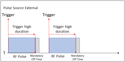
For M9383B/M9384B. When the Pulse Source is External, a signal provided on the connector below modulates the RF Output.
Pulse In connector for M9384B
M9314B Trig 1 connector for M9383B
When the external signal is logic high (TTL high) the RF Output will be on, when the external signal is logic low (TTL low) the RF Output will be off. This logic can be inverted with the Polarity setting.
The polarity of the external TTL signal can be selected. Normal enables the RF Output when the external signal is TTL high, or Inverted enabled the RF Output when the external signal is TTL low.
|
SCPI Command |
[:SOURce][:RF<channel>]:PULM:EXTernal:POLarity NORMal|INVerted [:SOURce][:RF<channel>]:PULM:EXTernal:POLarity? |
|
SCPI Example |
PULM:EXT:POL NORM PULM:EXT:POL? |
|
Preset |
NORM |
|
State Saved |
Yes |
|
Range |
Normal|Inverted |
|
Notes |
For M9484C, this command has no effect. |
|
Initial S/W Revision |
A.01.00 |
The instrument’s internal circuitry provides the pulsing of the RF Output.
Sets the pulse type from the choices in the following table.
|
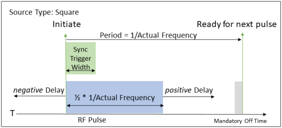
Square |
Sets Square as the pulse modulation source. This is an immediately initiated pulse with a 50% duty cycle. The period is determined by the requested frequency. |
|
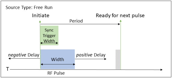
Free Run |
Sets Free Run as the pulse modulation source. This is an immediately initiated pulse. You can define the period, width, and delay. |
|
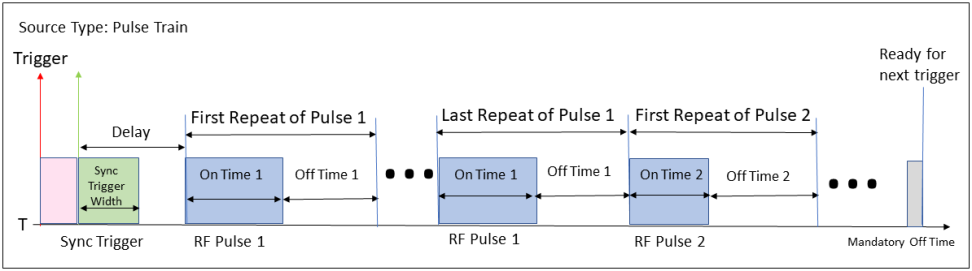
Pulse Train |
With Option 320, produces an RF pulse train (up to 2047 distinct cycles) with user-defined widths at the RF OUTPUT connector when a trigger condition occurs. The Pulse Train Trigger Mode selection determines when the pulse train is initiated. When the Pulse Train Trigger Mode is External, the external signal must be connected to:
Triggers which occur while pulse train is executing are ignored. |
|
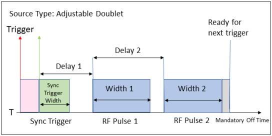
Adjustable Doublet |
Sets Adjustable Doublet as the pulse modulation source. This selection produces two pulses at the RF OUTPUT connector for each trigger event at the:
The first pulse has a user-defined width and delay (from the rising edge of the Pulse Sync Out signal). The second pulse has a user-defined width and delay (from the rising edge of the first pulse). Triggers which occur while adjustable doublet is executing are ignored.
|
|
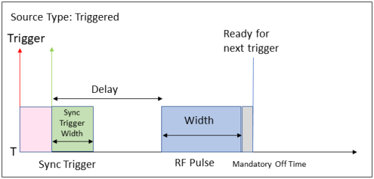
Triggered |
Sets Triggered as the pulse modulation source. This selection produces an RF pulse with a user-defined width and delay at the RF OUTPUT connector when a valid trigger signal occurs at the:
Triggers which occur while the second pulse is executing are ignored. |
|
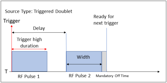
Triggered Doublet |
For M9383B/M9384B only. Sets Triggered Doublet as the pulse modulation source. This produces two pulses at the RF OUTPUT connector for each trigger event at the:
The first pulse follows the external trigger signal. The second pulse has user-defined width and delay parameters. Triggers which occur while the second pulse is executing are ignored. |
|
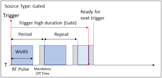
Gated |
For M9383B/M9384B only. Sets Gated as the pulse modulation source. User-defined period and width occurs at the RF OUTPUT connector when a logic-high signal is applied to the
The pulsing repeats until the signal becomes logic-low, if the logic-low occurs during a pulse one time the pulse will be truncated. |
For M9484C, with Source Types of Adjustable Doublet, Triggered, and Pulse Train in Triggered Mode the minimum Pulse Repetition Interval (from one trigger initiation to the next) is 4.010 us.
|
SCPI Command |
[:SOURce][:RF<channel>]:PULM:SOURce:INTernal SQUare|FRUN|PTRain|ADOublet|TRIGgered|DOUBlet|GATEd [:SOURce][:RF<channel>]:PULM:SOURce:INTernal? |
|
SCPI Example |
PULM:SOUR:INT SQU PULM:SOUR:INT? |
|
Preset |
FRUN |
|
Notes |
PTRain requires Option 320; attempting to set PTRain without Option 320 raises the error -224,"Illegal parameter value" For M9484C, if the type is set to PTRain and the currently configured Pulse Train does not meet the minimum length, the following error occurs: -222, ”Data out of range; Requested Pulse Train does not meet the minimum required total length 4.01 us.” For M9484C DOUBlet is not available; attempting to set DOUBlet raises the error -224,"Illegal parameter value" |
|
State Saved |
Yes |
|
Initial S/W Revision |
A.01.00 |
For Pulse Source Types of Free Run, Adjustable Doublet, Triggered, Triggered Doublet, and Gated, sets the pulse width for the internally generated pulse modulation. The command, used with the UP|DOWN parameters, will change the pulse width by a user-defined step value. Refer to pulse width increment for setting the value associated with the UP and DOWN choices.
Use PWIDth1 with the DOUBlet parameter and PWIDth1 and PWIDth2 with the ADOublet parameter. Refer to internal source type.
The coupling of width is dependent upon the source type, in the following description the Mandatory Off Time is 10 ns:
Constraint: Width ≤ Period – Positive value of Delay – Mandatory Off Time
If the entered value for the Width is > Period – Positive value of Delay – Mandatory Off Time, the Delay is reduced to a minimum of 0 seconds. If the entered value of Width is still larger than the constraint, Width is set to Period – Mandatory Off Time. Thus, if larger values of Width are desired, set the Period value first.
Constraint: Delay1 + Maximum(Width1 or (Delay2 + Width2)) + Mandatory Off Time must be ≥ the minimum of one width + Mandatory Off Time, and ≤ 42 seconds
If the entered value for Width1 is > 42 seconds – Mandatory Off Time – the current value for Delay1, Delay1 is reduced.
If the entered value for Width2 is > 42 seconds – Delay1 – Mandatory Off Time – the current value for Delay2, Delay2 is reduced. If the result yields Delay2 of 0 seconds, and the entered Width2 is still larger than allowed, Width2 is limited to the remaining value.
Constraint: Delay + Width + Mandatory Off Time must be ≥ the minimum Width + Mandatory Off Time, and ≤ 42 seconds
If the entered value for Width is > 42 seconds – Mandatory Off Time – the current value for Delay, Delay is reduced.
Constraint: Width ≤ Period – Mandatory Off Time
If the entered value for the Width is > Period – Mandatory Off Time, the Width is set to Period – Mandatory Off Time. Thus, if larger values of Width are desired, set the Period value first.
|
SCPI Command |
[:SOURce][:RF<channel>]:PULM:INTernal:PWIDth[1]|2 <time> [:SOURce][:RF<channel>]:PULM:INTernal:PWIDth[1]|2? |
|
SCPI Example |
PULM:INT:PWID 100 ms PULM:INT:PWID? |
|
Notes |
For M9383B/M9384B, a power search is recommended for signals with pulse widths less than one microsecond. |
|
Couplings |
Couplings are based on Source Type. |
|
Dependencies |
When the Source Type is changed the current value of Width is evaluated. UP and DOWN are based on Width Increment Step |
|
Preset |
200 ns |
|
State Saved |
Yes |
|
Min |
For M9383B/M9384B: 30 ns For M9484C: Option PME: 30 ns Option PMR: 20 ns |
|
Max |
42 s - 10 ns |
|
Resolution |
10 ns |
|
Initial S/W Revision |
A.01.00 |
|
Modified at S/W Revision |
A.06.00 |
|
History |
Changed preset from "50 ns (PMR) 100 ns (PME)" at A.06.00 |
Remote command only.
Sets the step increment for the pulse width. The step value, set by this command, is used with the UP and DOWN choices available in the pulse width command.
|
SCPI Command |
[:SOURce][:RF<channel>]:PULM:INTernal:PWIDth:STEP <time> [:SOURce][:RF<channel>]:PULM:INTernal:PWIDth:STEP? |
|
SCPI Example |
PULM:INT:PWID:STEP 100 ns PULM:INT:PWID:STEP? |
|
Notes |
The step value, set with this command, is not affected by a power-on, preset, or *RST command. |
|
Preset |
1000 ns |
|
Resolution |
10 ns |
|
State Saved |
No |
|
Min |
20 ns |
|
Max |
42 s |
|
Initial S/W Revision |
A.01.00 |
|
Modified at S/W Revision |
A.11.00 |
|
History |
Changed the maximum value in A.11.00 |
For Pulse Source Types of Free Run and Gated, sets the pulse period for the internally generated pulse modulation. The command, used with the UP|DOWN parameters, will change the pulse period by a user–defined step value. Refer to pulse period increment for setting the value associated with the UP and DOWN choices.
The coupling of period is dependent upon the source type, in the following description the Mandatory Off Time is 10 ns:
For positive values of Delay, if the entered value for Period is < current value for Delay + Width + Mandatory Off Time, the Delay is reduced to a minimum of 0 seconds. If the entered Period is still less than Width + Mandatory Off Time, Width is set to the Period – Mandatory Off Time.
For negative values of Delay, if the entered value for Period is < current value for Width + Mandatory Off Time, the Width is reduced.
If the entered value for the Period is < the current value for Width + Mandatory Off Time, the Width value is reduced to Period – Mandatory Off Time.
|
SCPI Command |
[:SOURce][:RF<channel>]:PULM:INTernal:PERiod <time> [:SOURce][:RF<channel>]:PULM:INTernal:PERiod? |
|
SCPI Example |
PULM:INT:PER .5s PULM:INT:PER? |
|
Notes |
The pulse generator works off a 100 MHz clock, therefore pulse on and off times will have a 10 ns resolution. The minimum period is essentially twice the minimum pulse width as licensed to accommodate an on and off pulse at the minimum. |
|
Couplings |
Couplings are based on Source Type. |
|
Dependencies |
UP and DOWN are based on Pulse Period Increment Step |
|
Preset |
4000 ns |
|
State Saved |
Yes |
|
Min |
M9383B VXG-m and M9384B VXG: 40 ns M9484C: Option PME: 40 ns Option PMR: 30 ns |
|
Max |
42 s |
|
Resolution |
10 ns |
|
Initial S/W Revision |
A.01.00 |
|
Modified at S/W Revision |
A.06.00 |
|
History |
Changed min value from 60 ns at A.06.00 |
Remote command only.
Sets the step value for the internal pulse period. The step value, set with this command, is used with the UP and DOWN choices available in the pulse period command.
|
SCPI Command |
[:SOURce][:RF<channel>]:PULM:INTernal:PERiod:STEP[:INCRement] <time> [:SOURce][:RF<channel>]:PULM:INTernal:PERiod:STEP[:INCRement]? |
|
SCPI Example |
PULM:INT:PER:STEP .1s PULM:INT:PER:STEP? |
|
Notes |
The step value set with this command is not affected by a power-on, preset, or *RST command. |
|
Preset |
1000 ns |
|
State Saved |
No |
|
Min |
10 ns |
|
Max |
42 s |
|
Resolution |
10 ns |
|
Initial S/W Revision |
A.01.00 |
|
Modified S/W Revision |
A.11.00 |
|
History |
Set the minimum value at A.11.00 |
For Pulse Source Types of Square, Free Run, Pulse Train, Adjustable Doublet, Triggered, and Triggered Doublet, sets the pulse delay for the internally generated pulse modulation. The command, used with the UP|DOWN parameters, will change the delay by a user-defined step value. Refer to pulse delay increment for setting the value associated with the UP and DOWN choices.
The value accepts ns (nanoseconds) to s (seconds) with a resolution of 10 ns.
For Pulse Source Types of Square and Free Run, Delay establishes the point in time where the Sync Trigger is raised relative to the Width: positive Delay values shift Width after Sync Trigger, negative Delay values shift Width before Sync Trigger. For the other pulse source types, Delay establishes the point in time where the Width begins.
Use Delay1 with Pulse Type of Triggered Doublet, and Delay1 and Delay2 with Pulse Type of Adjustable Doublet. Delay2 is valid only when Pulse Type is Adjustable Doublet.
The coupling of delay is dependent upon the source type, in the following description the Mandatory Off Time is 10 ns:
Constraint: |Delay| ≤ (1/Actual Frequency) – Sync Trigger Width – Mandatory Off Time
If the entered value for the |Delay| is > (1/Actual Frequency) – the current value of Sync Trigger Width – Mandatory Off Time, Sync Trigger Width is reduced, to the limit of minimum Sync Trigger Width. If the entered value for |Delay| is still larger than the constraint, Delay will be clipped. Thus, if larger values of Delay are desired, set the Requested Frequency value first. Note: negative values for Delay must be < - (Sync Trigger Width + Mandatory Off Time).
For positive values of Delay:
Constraint: Delay ≤ (1/2 * 1/Actual Frequency) – Mandatory Off Time
If the entered value for Delay is > (1/2 * 1/Actual Frequency) – Mandatory Off Time, the Delay will be clipped. Thus, if larger values of Delay are desired, set the Requested Frequency value first.
For negative values of Delay:
Constraint: |Delay| ≤ (1/Actual Frequency) – Mandatory Off Time
If the entered value for |Delay| is > (1/Actual Frequency) – Mandatory Off Time, the Delay will be clipped. Thus, if larger negative values of Delay are desired, set the Requested Frequency value first.
Constraint: |Delay| ≤ Period – Sync Trigger Width – Mandatory Off Time
If the entered value for the |Delay| > Period – current value of Sync Trigger Width – Mandatory Off Time, Sync Trigger Width is reduced, to the limit of minimum Sync Trigger Width. If the entered value for |Delay| is still larger than the constraint, Delay will be clipped. Thus, if larger values of Delay are desired, set the Period value first. Note: negative values for Delay must be < - (Sync Trigger Width + Mandatory Off Time).
When pulse train trigger mode is Triggered, Delay specifies the time after a trigger is received before the first Pulse Train On Time starts.
When pulse train trigger mode is Free Run or Gated, Delay is not applicable.
Constraint: Delay1 + Maximum(Width1 or (Delay2 + Width2)) + Mandatory Off Time must be ≥ the minimum of one width + Mandatory Off Time, and ≤ 42 seconds
If the entered value for Delay1 is > 42 seconds – the current value for Width1 – Mandatory Off Time, Width1 is reduced to the limit of the minimum Width or the sum of Delay2 + Width2.
If the entered value for Delay2 is > 42 seconds – Delay1 – the current value for Width2 – Mandatory Off Time, Width2 is reduced to the limit of minimum Width.
Constraint: Delay ≤ 42 seconds – Width – Mandatory Off Time
If the entered value for the Delay > 42 seconds – current value of Width – Mandatory Off Time, Width is reduced to the limit of minimum Width. If the entered value for Delay is still larger than the constraint, the Delay will be clipped
|
SCPI Command |
[:SOURce][:RF<channel>]:PULM:INTernal:DELay[1]|2 <time> [:SOURce][:RF<channel>]:PULM:INTernal:DELay[1]|2? |
|
SCPI Example |
PULM:INT:DEL 4 PULM:INT:DEL? |
|
Couplings |
Couplings are based on Source Type. |
|
Dependencies |
When the Source Type is changed the current value of Delay is evaluated. UP and DOWN are based on Pulse Delay Increment Step |
|
Preset |
Delay1: 0 Delay2: 260 ns |
|
State Saved |
Yes |
|
Min |
For Pulse Source Type:
|
|
Max |
For Pulse Source Type:
|
|
Resolution |
10 ns |
|
Initial S/W Revision |
A.01.00 |
|
Modified at S/W Revision |
A.06.00, A.11.00 |
|
History |
Changed Preset from "110 ns (PMR) or 300 ns (PME)" at A.06.00 Enabled negative values at A.11.00 |
Remote command only.
Sets the step increment for the pulse delay. The step value, set by this command, is used with the UP and DOWN choices in the :PULM:INTernal:DELay[1]|2 command.
|
SCPI Command |
[:SOURce][:RF<channel>]:PULM:INTernal:DELay:STEP <time> [:SOURce][:RF<channel>]:PULM:INTernal:DELay:STEP? |
|
SCPI Example |
PULM:INT:DEL:STEP 10 ns PULM:INT:DEL:STEP? |
|
Notes |
The step value set with this command is not affected by a signal generator power-on, preset, or *RST command. |
|
Preset |
1000 ns |
|
State Saved |
Persistent, survives preset and power cycle but not saved in the instrument state. |
|
Min |
10 ns |
|
Max |
42 s |
|
Resolution |
10 ns |
|
Initial S/W Revision |
A.01.00 |
|
Modified at S/W Revision |
A.11.00 |
|
History |
Changed the maximum value in A.11.00 |
For the Square pulse source type, sets the pulse rate for the internally generated square wave. The command, used with the UP|DOWN parameters, will change the frequency by a user-defined step value. Refer to Requested Frequency Increment for setting the value associated with the UP and DOWN choices.
This value sets the pulse rate of the square wave with a 50% duty cycle.
If the entered value for Requested Frequency affects Actual Frequency such that (1/Actual Frequency) is < current value for |Delay| + Mandatory Off Time, the |Delay| is set to (1/Actual Frequency) – Mandatory Off Time. In addition, if the entered value for Requested Frequency affects Actual Frequency such that (1/Actual Frequency) is < current value Sync Trigger Width + Mandatory Off Time, the Sync Trigger Width is set to (1/Actual Frequency) – Mandatory Off Time.
|
SCPI Command |
[:SOURce][:RF<channel>]:PULM:INTernal:FREQuency <freq> [:SOURce][:RF<channel>]:PULM:INTernal:FREQuency? |
|
SCPI Example |
PULM:INT:FREQ 2 PULM:INT:FREQ? |
|
Notes |
The pulse generator works off a 100 MHz clock, therefore pulse on and off times will have a 10 ns resolution, or a periodicity resolution of 20 ns. So setting 9 MHz would result in an actual frequency of 8.3333 MHz because 9 MHz at 50% duty cycle would require on and off pulses of 55.555 ns each. The clock resolution is 10 ns, therefore the on and off pulses ended up being rounded to 60 ns each or a total period of 120 ns. A periodicity of 120 ns = 8.33333 MHz. See Actual Frequency query to obtain the resultant value. |
|
Couplings |
Changes to Requested Frequency may have an effect on Delay and Sync Trigger Width. |
|
Dependencies |
UP and DOWN are based on Requested Frequency Increment Step |
|
Preset |
1 kHz |
|
State Saved |
Yes |
|
Min |
0.1 Hz |
|
Max |
For M9383B/M9384B: 16.6666666666667 MHz For M9484C: Option PME: 16.6666666666667 MHz Option PMR: 25 MHz |
|
Resolution |
0.1 Hz |
|
Initial S/W Revision |
A.01.00 |
|
Modified S/W Revision |
A.11.00 |
|
History |
Resolution changed at A.11.00 |
Remote command only.
Sets the step value for Requested Frequency. The step value, set with this command, is used with the UP and DOWN choices in the :PULM:INTernal:FREQuency command.
|
SCPI Command |
[:SOURce][:RF<channel>]:PULM:INTernal:FREQuency:STEP[:INCRement] <freq> [:SOURce][:RF<channel>]:PULM:INTernal:FREQuency:STEP[:INCRement]? |
|
SCPI Example |
PULM:INT:FREQ:STEP MIN PULM:INT:FREQ:STEP? |
|
Notes |
The step value set with this command is not affected by a power-on, preset, or *RST command. |
|
Preset |
500 Hz |
|
State Saved |
No |
|
Min |
0.1 Hz |
|
Max |
10 MHz |
|
Resolution |
0.1 Hz |
|
Initial S/W Revision |
A.01.00 |
|
Modified S/W Revision |
A.11.00 |
|
History |
Resolution changed at A.11.00 |
Query only.
The pulse on and off times have a 10 ns resolution, or a periodicity resolution of 20 ns. Therefore, the actual frequency may be different from the value specified in the Requested Frequency.
|
SCPI Command |
[:SOURce][:RF<channel>]:PULM:INTernal:FREQuency:ACTual? |
|
SCPI Example |
PULM:INT:FREQ:ACT? |
|
Resolution |
0.1 Hz |
|
Initial S/W Revision |
A.01.00 |
|
Modified S/W Revision |
A.11.00 |
|
History |
Resolution changed at A.11.00 |
Pulse train requires Option 320 and is dependent on already having Option PME/PMR.
Pulse Train establishes a series of pulses to be applied to the RF Output when the trigger condition is met. The pulse train can be 1 to 2047 pulses. When defining the pulse train, the number of pulses is established by the setting with the most elements in the parameter list.
For M9484C, the total of all the On Times and Off Times, including repetitions, must be at least 30 ns for Trigger Mode of Free Run, or 4.010 us for the Trigger Mode of Triggered. Ensure your composition of the Pulse Train is at least this length.
Sets the pulse on values for the current list of pulse train on times. If this list is shorter than the other lists, then the last element will be repeated as necessary to match the length of the Off Time or Repetitions. The query returns the count of pulse cycle elements in the list of on times.
For M9484C, the total of all the On Times and Off Times, including repetitions, must be at least 30 ns for Trigger Mode of Free Run, or 4.010 us for Trigger Mode of Triggered.
|
SCPI Command |
[:SOURce][:RF<channel>]:PULM:INTernal:TRAin:ONTime <real>[,<real>][…] [:SOURce][:RF<channel>]:PULM:INTernal:TRAin:ONTime? |
|
SCPI Example |
PULM:INT:TRA:ONT 4e-08 PULM:INT:TRA:ONT? |
|
Notes |
MIN | MAX | DEF | UP | DOWN are not supported. |
|
Preset |
200 ns |
|
State Saved |
Yes |
|
Min |
For M9383B/M9384B: 30 ns For M9484C: Option PME: 30 ns Option PMR: 20 ns |
|
Max |
42 – 10 ns |
|
Resolution |
1e-08 |
|
Initial S/W Revision |
A.01.00 |
|
Modified S/W Revision |
A.11.00 |
|
History |
Changed Preset value at A.11.00 |
This query returns the count of elements in the list of on times.
|
SCPI Command |
[:SOURce][:RF<channel>]:PULM:INTernal:TRAin:ONTime:POINts? |
|
SCPI Example |
PULM:INT:TRA:ONT:POIN? |
|
Initial S/W Revision |
A.01.00 |
Sets the pulse off values for the current list of pulse train off times (where the RF will be off). If this list is shorter than the other lists, then the last element will be repeated as necessary to match the length of the On Time or Repetitions. The query returns the count of pulse cycle elements in the list of off times.
For M9484C, the total of all the On Times and Off Times, including repetitions, must be at least 30 ns for Trigger Mode of Free Run, or 4.010 us for Trigger Modes of Triggered or Gate.
|
SCPI Command |
[:SOURce][:RF<channel>]:PULM:INTernal:TRAin:OFFTime <real>[,<real>][…] [:SOURce][:RF<channel>]:PULM:INTernal:TRAin:OFFTime? |
|
SCPI Example |
PULM:INT:TRA:OFFT 4e-08 PULM:INT:TRA:OFFT? |
|
Notes |
MIN | MAX | DEF | UP | DOWN are not supported. |
|
Preset |
For M9383B/M9384B: 10 ns For M9484C: 3.81 us |
|
State Saved |
Yes |
|
Min |
10 ns |
|
Max |
42 seconds – Pulse Train On Time Min |
|
Resolution |
1e-08 |
|
Initial S/W Revision |
A.01.00 |
This query returns the count of elements in the list of off times.
|
SCPI Command |
[:SOURce][:RF<channel>]:PULM:INTernal:TRAin:OFFTime:POINts? |
|
SCPI Example |
PULM:INT:TRA:OFFT:POIN? |
|
Initial S/W Revision |
A.01.00 |
Generates a user-defined list of the pulse repetitions. The maximum is a total count of 2047, so a list of "2047,1" would be too long. Lists that are too long will generate an error and only the first 2047 pulses will be played. If this list is shorter than the other lists, then the last element will be repeated as necessary to match the length of the On Time or Off Time list, whichever is longer.
|
SCPI Command |
[:SOURce][:RF<channel>]:PULM:INTernal:TRAin:REPetition <integer>[,<integer>][…] [:SOURce][:RF<channel>]:PULM:INTernal:TRAin:REPetition? |
|
SCPI Example |
PULM:INT:TRA:REP 100,20,3 PULM:INT:TRA:REP? |
|
Notes |
MIN | MAX | DEF | UP | DOWN are not supported. |
|
Preset |
1 |
|
State Saved |
Yes |
|
Min |
1 |
|
Max |
2047 |
|
Initial S/W Revision |
A.01.00 |
This query returns the count of elements in the list of repetitions.
|
SCPI Command |
[:SOURce][:RF<channel>]:PULM:INTernal:TRAin:REPetition:POINts? |
|
SCPI Example |
PULM:INT:TRA:REP:POIN? |
|
Initial S/W Revision |
A.01.00 |
Sets the list to a single pulse with On Time, Off Time, and Repetitions to their default values.
|
SCPI Command |
[:SOURce][:RF<channel>]:PULM:INTernal:TRAin:LIST:PRESet |
|
SCPI Example |
PULM:INT:TRA:LIST:PRES |
|
State Saved |
N/A |
|
Initial S/W Revision |
A.01.00 |
|
Modified S/W Revision |
A.11.00 Changed the parameters of the list to the default values of On Time, Off Time, and Repetition |
Sets the triggering mode for the Pulse Train feature.
|
FRUN |
Free Run triggering continuously plays the pulse train. |
|
TRIGgered |
Trigger runs the pulse train (after waiting the Pulse Delay) each time an external trigger is supplied (edge triggered) to Pulse Trigger. Triggers received during playback are lost. |
|
SCPI Command |
[:SOURce][:RF<channel>]:PULM:INTernal:TRAin:TRIGger FRUN|TRIGgered [:SOURce][:RF<channel>]:PULM:INTernal:TRAin:TRIGger? |
|
SCPI Example |
PULM:INT:TRA:TRIG FRUN PULM:INT:TRA:TRIG? |
|
Notes |
For M9484C, the total of all the On Times and Off Times, including repetitions, must be at least 30 ns for Trigger Mode of Free Run, or 4.010 us for the Trigger Mode of Triggered. Ensure your composition of the Pulse Train is at least this length. If the currently configured Pulse Train does not meet the minimum length the warning -222,”Data out of range; Requested Pulse Train does not meet the minimum required total length 4.01 us.” |
|
Preset |
TRIGgered |
|
State Saved |
Yes |
|
Initial S/W Revision |
A.01.00 |
Runs the pulse train once when Pulse Train is turned on and Pulse Train Trigger Mode is Triggered. If the pulse train is already running, neither this button nor SCPI command has any effect.
|
SCPI Command |
[:SOURce][:RF<channel>]:PULM:INTernal:TRAin:TRIGger:IMMediate |
|
SCPI Example |
PULM:INT:TRA:TRIG:IMM |
|
Dependencies |
Grayed out when Pulse Train Trigger Mode is not Triggered. |
|
Initial S/W Revision |
A.04.00 |
During pulse modulation, when the instrument’s RF Output is on, a logic-high signal is applied to a connector on the instrument. This is also referred to as Pulse Video.
For M9383B:
Options F14 or F20, for channel 1, the connector is M9043A Trig 1
Options F14 or F20 and Option 002, for channel 2, the connector is M9043A Trig 2
Options F32 or F44 the connector is M9323A Trig 1
For M9384B the connector is Pulse Video Out
For M9484C the connector is Event 2
For M9383B/M9384B, the output can be turned on and off. For M9484C, the output is always enabled.
For M9383B/M9384B only. enables or disables the trigger used to output the pulse modulation signal.
|
SCPI Command |
[:SOURce][:RF<channel>]:PULM:OUTPut:ENABle ON|OFF|1|0 [:SOURce][:RF<channel>]:PULM:OUTPut:ENABle? |
|
SCPI Example |
PULM:OUTP:ENAB ON PULM:OUTP:ENAB? |
|
Preset |
OFF |
|
State Saved |
Yes |
|
Initial S/W Revision |
A.01.00 |
For Pulse Source Types of Square, Free Run, Pulse Train, Adjustable Doublet, and Triggered, the instrument provides a logic high signal on a connector which can be used to trigger external equipment when the signal generator’s pulse operation has initiated.
For M9383B:
Options F14 or F20 the connector is M9343A Trig 2
Options F32 or F44 the connector is M9323A Trig 2
For M9384B the connector is Pulse Sync Out
For M9484C the connector is Event 1
For M9383B/M9384B, the output can be turned on and off. For M9484C, the output is always enabled.
For M9383B/M9384B only. Enables or disables the pulse modulation synchronization signal. Sync signal is generated at the predefined timing shown in the diagrams for Source Type.
|
SCPI Command |
[:SOURce][:RF<channel>]:PULM:SYNC:ENABle ON|OFF|1|0 [:SOURce][:RF<channel>]:PULM:SYNC:ENABle? |
|
SCPI Example |
PULM:SYNC:ENAB ON PULM:SYNC:ENAB? |
|
Preset |
OFF |
|
State Saved |
Yes |
|
Initial S/W Revision |
A.01.00 |
Defines the width of the synchronization pulse in seconds. The command, used with the UP|DOWN parameters, will change the width by a user–defined step value. Refer to Sync Trigger Width Increment for setting the value associated with the UP and DOWN choices.
The coupling of sync trigger width is dependent upon the source type, in the following description the Mandatory Off Time is 10 ns:
Constraint: Sync Trigger Width ≤ (1/Actual Frequency) – Mandatory Off time
If the entered value for the Sync Trigger Width is > (1/Actual Frequency) – Mandatory Off Time, Sync Trigger Width will be clipped. Thus, if larger values of Sync Trigger Width are desired, set the Requested Frequency value first.
Constraint: Sync Trigger Width ≤ Pulse Period – Mandatory Off Time
If the entered value for the Sync Trigger Width is > the current value for the Period – Mandatory Off Time, Sync Trigger Width will be clipped. Thus, if larger values of Sync Trigger Width are desired, set the Period value first.
Constraint: Sync Trigger Width ≤ 42 seconds – Mandatory Off Time
|
SCPI Command |
[:SOURce][:RF<channel>]:PULM:SYNC:WIDTh <time> [:SOURce][:RF<channel>]:PULM:SYNC:WIDTh? |
|
SCPI Example |
PULM:SYNC:WIDT 3.2 us PULM:SYNC:WIDT? |
|
Dependencies |
When the Source Type is changed the current value of Sync Trigger Width is evaluated. |
|
Preset |
200 ns |
|
State Saved |
Yes |
|
Min |
For M9383B/M9384B: 30 ns For M9484C: Option PME: 30 ns Option PMR: 20 ns |
|
Max |
42 s – 10 nsec |
|
Resolution |
10 ns |
|
Initial S/W Revision |
A.01.00 |
|
Modified at S/W Revision |
A.06.00 |
|
History |
Changed Preset from 50 ns at A.06.00 |
Remote command only.
Sets the step increment for the sync width. The step value, set by this command, is used with the UP and DOWN choices available for Sync Trigger Width.
|
SCPI Command |
[:SOURce][:RF<channel>]:PULM:SYNC:WIDTh:STEP <step> [:SOURce][:RF<channel>]:PULM:SYNC:WIDTh:STEP? |
|
SCPI Example |
PULM:SYNC:WIDT:STEP 100 ns PULM:SYNC:WIDT:STEP? |
|
Notes |
The step value, set with this command, is not affected by a power-on, preset, or *RST command. |
|
Preset |
10 ns |
|
Resolution |
10 ns |
|
State Saved |
No |
|
Min |
10 ns |
|
Max |
41 s |
|
Initial S/W Revision |
A.11.00 |
For M9484C only. The pulse trigger is connected to the selected trigger source when pulse is on. If a connector is routed to an output when the pulse feature is turned on with an external source with a pulse type besides Square, Free Run, or Pulse Train, then the output will be disconnected, and the pulse input will be operational. An error will be reported when this happens. (See Trigger Connectors.)
|
SCPI Command |
[:SOURce][:RF<channel>]:PULM:TRIGger[:SOURce] KEY|BUS|EXTernal [:SOURce][:RF<channel>]:PULM:TRIGger[:SOURce]? |
|
SCPI Example |
PULM:TRIG EXT PULM:TRIG? |
|
Couplings |
When Pulse is Enabled and Pulse Trigger Source is set to External, if the Trig 1 connector was being used (not None) as an output, then the Trigger Output Routing of that connector is set to None and a Settings Conflict message is generated. |
|
Preset |
EXT |
|
State Saved |
Yes |
|
Initial S/W Revision |
A.11.00 |